Countersink holes let flat-head screws sit flush with the surface. Learn standard angles, ANSI and ISO size charts, drawing callouts, and design tips for CNC machined parts.
Almost every mechanical drawing that uses flat-head screws calls for a countersink hole. It keeps the fastener head flush with the surface so nothing sticks out to interfere with mating parts, moving components, or the finished appearance.
They are one of the most common types of holes in engineering, used in CNC machining, sheet metal fabrication, and injection molding across aerospace, automotive, electronics, and furniture manufacturing.
This guide covers countersink hole types, standard angles, size charts, drawing callouts, machining methods, tolerances, common design mistakes, and how countersinks compare with counterbore holes.
What Is a Countersink Hole?
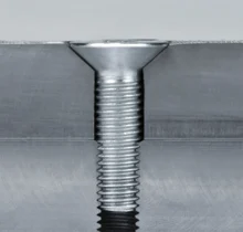
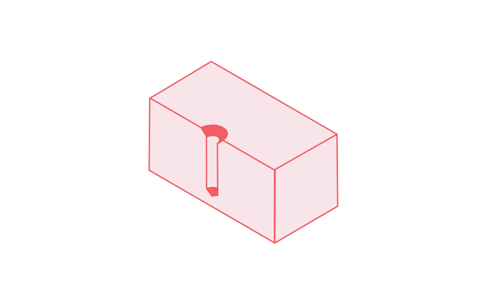
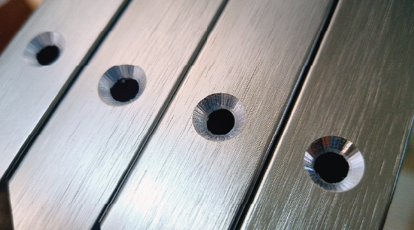
A countersink hole is a conical recess formed at the top of a drilled hole. The angled walls taper outward from the pilot hole to create a cone-shaped seat on the workpiece surface. This geometry matches the underside of a flathead screw or rivet, so when the fastener is driven in, the head seats into the cone and rests level with the surrounding material.
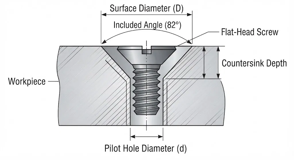
Three parameters define a countersink hole:
Diameter is measured at the surface, where the major diameter must match the fastener head size. If the countersink diameter is smaller than the head, the fastener sits proud. If the diameter is too large, the head drops below the surface and loses contact with the angled walls, reducing clamping force.
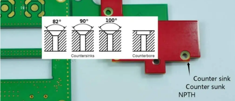
Angle must match the fastener standard: 82° for ANSI imperial fasteners, 90° for ISO metric fasteners, 100° for BA threaded fasteners, and 120° for sheet metal rivets.
Depth controls whether the head sits flush, proud, or recessed. Depth is typically a derived dimension. Once diameter and angle are specified, depth follows from the geometry.
The drilled hole below the countersink is typically a clearance hole or a threaded hole, depending on the fastener arrangement.
Symbol and Drawing Callout
The countersink symbol is ⌵. On a technical drawing, it indicates a conical recess at the hole opening.
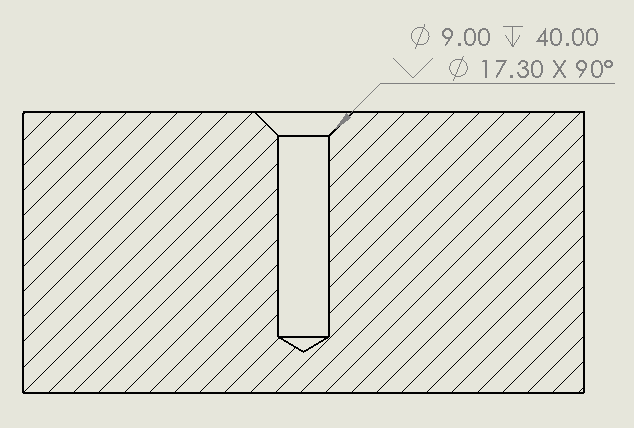
A standard countersink callout looks like this:
⌵ Ø17.30 × 90°
This means: countersink to a 17.30 mm diameter at a 90° included angle.
A complete manufacturing callout includes:
Diameter of the cylindrical (pilot) hole
Pilot hole depth
Countersink diameter
Countersink angle
Example: Ø9.0 ↓ 40.0 / ⌵ Ø17.3 × 90°
This tells the machinist: drill a 9.0 mm pilot hole to 40.0 mm depth, then countersink to 17.3 mm diameter at 90°.
Countersink HolesBest practice: Specify diameter and angle on the drawing; let depth follow from the geometry. Over-constraining all three independently (diameter, angle, and depth) conflicts with the tool geometry and creates inspection problems. Under GD&T, positional tolerances are applied to the pilot hole axis, and the countersink follows that axis. If the hole position is off, the countersink seating is off.
Types of Countersink Holes
Countersink holes are classified by how they are formed, the geometry of the recess, and the machining direction. Choosing the right type depends on the material, production volume, and access to the hole location.
Standard Machined Countersink
The most common type. A countersink bit cuts a conical recess into the material after the pilot hole is drilled. Used in CNC machining, drill press work, and manual drilling for metals, plastics, and wood.
Formed (Dimpled) Countersink
Instead of cutting material away, a forming tool presses the sheet metal into a conical shape around the hole. Common in thin sheet metal work where removing material would weaken the part. Formed countersinks preserve material thickness and are faster to produce in high-volume stamping operations.
Back Countersink
A countersink cut on the far side of the workpiece, opposite the tool entry. Used when the fastener head must be recessed on a surface that cannot be accessed from the front, such as hidden fasteners inside enclosed assemblies. Requires specialized tooling that reaches through the pilot hole.
Combination Drill and Countersink
A single tool that drills the pilot hole and cuts the countersink in one operation. Saves cycle time in high-volume production and ensures concentricity between the pilot hole and the countersink. Common in woodworking and CNC production runs.
Cross-Hole Countersink
A countersink cutter with a hole through the cone that allows it to pass over a pin or guide. Used for controlled alignment in tight-tolerance applications where the countersink must be perfectly concentric with an existing feature.
When to Use Countersink Holes
Use a countersink hole when the fastener head cannot protrude above the surface:
The surface must be flush. Mating parts that sit flat against each other cannot have protruding fastener heads between them. Any protrusion creates a gap that affects alignment and sealing.
Moving parts are nearby. Raised screw heads catch on cables, seals, and adjacent components. Countersinking eliminates the interference.
Aerodynamic or hydrodynamic performance matters. In aerospace and marine applications, a protruding rivet head at high speed creates drag. Every fastener on an aircraft skin panel is countersunk.
Safety is a concern. Raised fastener heads on panels, walkways, and equipment housings are cut and snag hazards. Flush heads remove the risk.
Aesthetics matter. Consumer electronics, furniture, and enclosures look unfinished with visible screw heads. Countersinks allow fasteners to be hidden under plugs, filler, or caps.
Self-centering is needed. The conical shape of a countersink naturally centers the fastener as it is driven in. This is an advantage over standard clearance holes when precise fastener alignment matters.
Countersink Hole Dimensions and Size Charts
The countersink diameter must match the fastener head. Material thickness limits how deep the recess can go before the head loses support or the part is weakened. If the countersink is too small, the screw head sits proud of the surface. If it is too large, the head loses wall contact and the joint loses clamping force.
The tables below list the standard countersink dimensions for socket flat head fasteners under ANSI and ISO specifications.
Table 1: Socket Flat Head Countersink (ANSI Inch, by Fastener Size Number)
Fastener Size
Countersink Diameter (in)
Countersink Angle (°)
#0
5/32
82
#1
3/16
82
#2
7/32
82
#3
1/4
82
#4
9/32
82
#5
5/16
82
#6
11/32
82
#8
3/8
82
#10
7/16
82
Table 2: Socket Flat Head Countersink (ANSI Inch, by Thread Size)
Thread Size
Countersink Diameter (in)
Countersink Angle (°)
1/4″
9/16
82
5/16″
11/16
82
3/8″
27/32
82
7/16″
29/32
82
1/2″
1
82
5/8″
1-1/4
82
3/4″
1-1/2
82
7/8″
1-3/4
82
1″
2
82
1-1/8″
2-1/4
82
1-1/4″
2-1/2
82
Table 3: Socket Flat Head Countersink (ISO Metric, by Thread Size)
Thread
Countersink Diameter (mm)
Countersink Angle (°)
M3
6.94
90
M3.5
7.95
90
M4
9.18
90
M5
11.47
90
M6
13.71
90
M8
18.25
90
M10
22.73
90
M12
27.21
90
M16
33.99
90
M20
40.71
90
How to Machine a Countersink Hole
Countersink holes are produced using CNC milling machines, drill presses, or handheld drills, depending on the precision required and the production volume. The basic process is the same regardless of the equipment.
Step 1: Drill the Pilot Hole
Select a drill bit sized to the fastener shank or the required clearance hole diameter. Drill the pilot hole to the specified depth. Secure the workpiece with clamps or a vise to prevent movement.
Step 2: Select the Countersink Bit
Choose a countersink bit that matches the required angle (82° for ANSI, 90° for ISO) and has a cutting diameter at least as large as the fastener head. Single-flute bits work better in harder materials and produce less chatter. Multi-flute bits (3, 5, or 6 flutes) cut faster and leave a smoother finish in softer materials.
Step 3: Set Depth Control
On a CNC machine or drill press, set the depth stop so the countersink reaches the correct major diameter without over-cutting. On a handheld drill, mark the bit with tape as a visual depth guide. Over-cutting weakens the surrounding material and causes the fastener head to sit below the intended position.
Step 4: Cut the Countersink
Run the countersink bit at a controlled speed. Use cutting fluid when machining metals to reduce heat, extend tool life, and improve surface finish. Apply steady, moderate feed pressure. Forcing the cutter causes chatter, rough surfaces, and bell-mouthed holes. Let the tool do the cutting.
Recommended spindle speeds vary by material:
Aluminum: 1,000–3,000 RPM
Mild steel: 300–800 RPM
Stainless steel: 200–500 RPM
Plastics: 500–1,500 RPM (low speed to prevent melting)
Wood: 1,500–3,000 RPM
Step 5: Inspect the Result
Check the countersink with a countersink gauge, optical comparator, or by test-fitting the fastener. The head should seat fully into the cone with even contact around the entire circumference. If the head rocks, the angle is wrong. If it sits proud, the diameter is too small. If it drops below the surface, the cut is too deep.
For production runs, first-article inspection should verify both the countersink diameter and angle against the drawing callout.
Material Considerations for Countersink Holes
Different materials respond differently to countersink cutting. The tool type, speed, feed rate, and whether cutting fluid is needed all depend on the workpiece material.
Aluminum machines easily but can produce burrs at the countersink edge. Use sharp, multi-flute countersink bits and moderate speed. Deburr after cutting if the edge will be a sealing or mating surface.
Steel and stainless steel require slower speeds, higher rigidity, and cutting fluid. Single-flute or two-flute bits reduce chatter in harder steels. Tool wear is faster, so inspect the cutter regularly. A dull countersink produces rough, inconsistent seats.
Plastics melt if the spindle speed or feed pressure is too high. Use sharp, polished cutters at low RPM with no cutting fluid (unless the plastic manufacturer recommends it). Straight-flute bits reduce the risk of grabbing.
Wood fibers compress unevenly during cutting, which can affect the final seat quality and surface finish. Use wood-specific countersink bits or combination drill-and-countersink bits. Drilling a pilot hole first reduces the risk of splitting, especially near edges and end grain.
Sheet metal (thin gauge) often cannot support a machined countersink without deforming. For material under 2.0 mm thick, formed (dimpled) countersinks preserve material integrity better than cut countersinks. Always check that the material thickness is sufficient to support the fastener head and maintain structural strength.
Countersink Tolerances and Standards
Typical Tolerances
For general-purpose countersink holes in CNC machining:
Diameter tolerance: ±0.1 mm (±0.004 in) for standard applications; ±0.05 mm (±0.002 in) for precision fits
Angle tolerance: ±1° for standard applications; ±0.5° for aerospace and precision work
Positional tolerance: Follows the pilot hole position under GD&T; typically ±0.15 mm for general machining
Overly tight tolerances on countersink depth add cost without functional benefit, since depth is derived from diameter and angle. Specify diameter and angle; let depth follow.
Applicable Standards
Key standards governing countersink hole dimensions and fastener compatibility:
ASME B18.6.3: Dimensions for countersunk head machine screws (inch series)
ASME B18.3: Socket head cap screws, including flat head (countersunk) variants
ISO 10642: Hexagon socket countersunk head screws (metric series)
ISO 15065: Sizes and tolerances for countersink features
DIN 74: Countersink dimensions for metric fasteners
MIL-S-1222: Military standard for countersunk fastener applications
When designing for a specific industry or customer, confirm which standard applies before specifying countersink dimensions.
Common Countersink Design Mistakes
Countersink Holes in Engineering Manufacturing
These are the countersink errors we see most often on incoming parts at Aria Manufacturing:
1. Angle Mismatch Between Countersink and Fastener
An 82° countersink paired with a 90° metric flat-head screw (or vice versa) prevents full contact. The screw head either wobbles on a narrow ring of contact or bottoms out before sitting flush. Always match the countersink angle to the fastener standard.
2. Over-Constraining the Drawing Callout
Specifying diameter, angle, and depth as independent dimensions over-constrains the feature. Once any two are fixed, the third is determined by geometry. If the drawing demands all three and the values conflict, the machinist has to choose which to prioritize, and the result may not match your intent.
3. Countersink Too Close to the Edge
Placing a countersink too near the part edge risks material breakout during machining. As a general rule, the center of the countersink should be at least 1.5× the major diameter from any edge.
4. Over-Cutting in Thin Material
In thin sheet metal or plastic panels, cutting a countersink that consumes most of the material thickness weakens the part around the fastener. The remaining wall cannot support clamping loads. For thin material, consider a formed countersink or switch to a counterbore with a low-profile fastener.
5. Missing Tolerances on the Drawing
A callout that says only "⌵ Ø17.3 × 90°" without tolerances leaves the machinist guessing. In production, this leads to variation between parts. Always specify at least a diameter tolerance and note whether the fastener should sit flush, slightly proud, or slightly recessed.
6. Using a Countersink Where a Counterbore Is Needed
Countersinks work with flat-head (conical underside) fasteners only. Socket head cap screws and hex bolts have flat undersides and require counterbores. Using the wrong hole type for the fastener is a common drawing error that causes rework.
When to Avoid Countersink Holes
Countersink holes are not always the best choice. Consider alternatives in these situations:
Very thin material. If the material thickness is less than the fastener head height, a machined countersink removes too much material. Use a formed countersink, a counterbore with a low-profile fastener, or a different attachment method.
High-load joints. Countersinks distribute load unevenly along the tapered face. For joints carrying heavy shear or tensile loads, a counterbore with a socket head cap screw and washer provides a larger, flat bearing surface and more consistent clamping force.
Soft or brittle materials. In soft plastics or cast materials, the conical stress concentration from a countersink can cause cracking. A counterbore spreads the load more evenly.
When fastener removal is frequent. Repeated insertion and removal of screws in a countersink can wear the conical seat, especially in softer metals like aluminum. A counterbore with a flat bottom resists this wear better.
Applications of Countersink Holes
Aerospace
Aircraft skins use countersunk rivets on every panel. At cruising speed, a protruding rivet head creates measurable aerodynamic drag. Flush riveting is a structural and performance requirement, not optional. Aerospace countersinks typically use 100° angles per NAS and AN rivet standards.
Automotive
Interior trim panels, brake components, and body panels use countersunk screws to keep surfaces smooth and prevent interference with adjacent parts. In under-hood applications, countersinks also reduce the risk of snagging wiring harnesses and hoses.
Consumer Electronics
Laptops, smartphones, and enclosures use countersunk screws to keep device casings flat and gap-free. A protruding screw head inside a device can also interfere with internal components or create short circuit risk against PCBs.
Sheet Metal Fabrication
Enclosures, brackets, and frames use countersink holes to keep assembly surfaces flush. In thin sheet metal, formed countersinks are preferred over machined ones because they preserve material strength and are faster to produce. Machined countersinks in sheet metal require sufficient material thickness, typically at least 1.5× the head height.
Furniture and Woodworking
Flat-head screws are countersunk into wood surfaces, then covered with wood plugs or filler to create a clean finish with no visible hardware. Combination drill-and-countersink bits produce the pilot hole and countersink in a single operation, saving time in production. Drilling a pilot hole first and keeping feed pressure low helps prevent splitting near edges.
Medical Devices
Surgical instruments and equipment housings use countersunk fasteners to eliminate crevices where bacteria can accumulate and to remove sharp edges that could contact patients. Countersink surfaces in medical applications are often polished to a mirror finish for cleanability.
Countersink Holes vs. Counterbore Holes
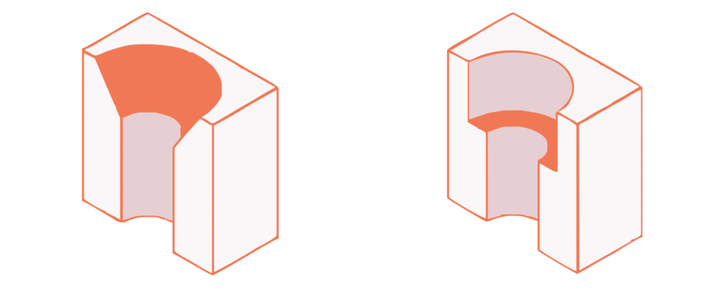
Countersink holes Vs Counterbore Holes
Countersink holes and counterbore holes both recess a fastener below the surface. The difference is the shape of the recess and the type of fastener each accommodates.
A countersink has angled walls forming a cone. It seats flat-head screws and flush rivets. The conical shape is self-centering, so the fastener aligns itself as it is tightened.
A counterbore has straight walls and a flat bottom. It is used with socket head cap screws and hex bolts. The screw head sits in a cylindrical pocket, and a washer can be placed at the bottom for additional load distribution.
Feature
Countersink Hole
Counterbore Hole
Shape
Cone-shaped, tapered sides
Cylindrical with a flat bottom
Callout symbol
⌵
⌴
Typical angles
82°, 90°, 100°, 110°, 120°
No angle; sides are straight
Depth
Shallow, just enough for the tapered head
Deeper, sized to fully recess the head
Used with
Flat-head screws, oval-head screws, rivets
Socket head cap screws, hex bolts, washers
Self-centering
Yes, conical shape aligns the fastener
No, requires precise hole positioning
Clamping force
Moderate, load distributes along tapered face
Higher, load spreads evenly on flat bottom
Manufacturing cost
Lower, single cutter, fast operation
Slightly higher, requires a separate boring step
Best for
Flush surfaces, thin material, aerodynamics
Heavy-duty joints, high-load applications
Frequently Asked Questions
Q:What is the difference between a countersink and a counterbore?A:A countersink creates a cone-shaped recess for flat-head fasteners. A counterbore creates a cylindrical pocket with a flat bottom for socket head cap screws or hex bolts. Countersinks are shallower and less expensive to machine; counterbores provide higher clamping force.
Q:What angle should a countersink be?
A:It depends on the fastener standard. Use 82° for ANSI/imperial flat-head screws, 90° for ISO metric flat-head screws, 100° for aerospace rivets (NAS/AN), and 120° for sheet metal rivets. Always match the countersink angle to the fastener.
Q:Can you countersink a hole in thin sheet metal?
A:Yes, but machined countersinks in thin material (under 2.0 mm) can weaken the part. Formed (dimpled) countersinks are preferred for thin gauge sheet metal because they reshape the material instead of removing it.
Q:How deep should a countersink hole be?
A:Deep enough for the fastener head to sit flush with the surface. In practice, specify the countersink diameter and angle on the drawing and let the depth follow from the geometry. Over-cutting causes the fastener to sit too low and reduces clamping force.
Q:What tools are used to make countersink holes?
A:Fluted countersink bits are the most common, available in single-flute and multi-flute configurations with standard angles of 60°, 82°, 90°, 100°, 110°, and 120°. Combination drill-and-countersink bits produce both features in one operation. CNC milling machines, drill presses, and handheld drills can all produce countersink holes.
Get Your Countersink Holes Right the First Time
Specifying countersink holes correctly requires matching the angle to the fastener, sizing the diameter to the head, and calling out tolerances that reflect the actual assembly requirement. Wrong angle, missing callout, or wrong hole type are the issues we see on incoming parts every week at Aria Manufacturing.
If you are designing a part and need a second opinion on your countersink specifications, or you are ready to get your parts quoted, send us your drawing. We review every countersink callout against the fastener spec and flag issues before machining begins. You will hear back within 24 hours.

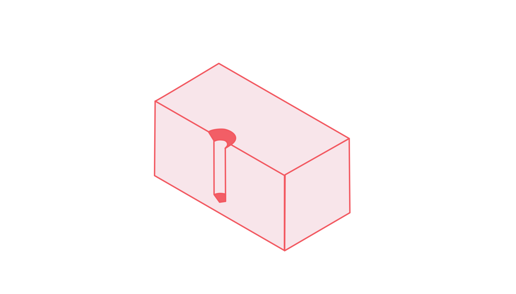
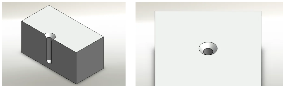 A countersink hole is a conical recess formed at the top of a drilled hole. The angled walls taper outward from the pilot hole to create a cone-shaped seat on the workpiece surface. This geometry matches the underside of a flathead screw or rivet, so when the fastener is driven in, the head seats into the cone and rests level with the surrounding material.
Three parameters define a countersink hole:
 Diameter is measured at the surface, where the major diameter must match the fastener head size. If the countersink diameter is smaller than the head, the fastener sits proud. If the diameter is too large, the head drops below the surface and loses contact with the angled walls, reducing clamping force.
Angle must match the fastener standard: 82° for ANSI imperial fasteners, 90° for ISO metric fasteners, 100° for BA threaded fasteners, and 120° for sheet metal rivets.
Depth controls whether the head sits flush, proud, or recessed. Depth is typically a derived dimension. Once diameter and angle are specified, depth follows from the geometry.
The drilled hole below the countersink is typically a clearance hole or a threaded hole, depending on the fastener arrangement.
 Countersink Holes
 Use a countersink hole when the fastener head cannot protrude above the surface:
The surface must be flush. Mating parts that sit flat against each other cannot have protruding fastener heads between them. Any protrusion creates a gap that affects alignment and sealing.
Moving parts are nearby. Raised screw heads catch on cables, seals, and adjacent components. Countersinking eliminates the interference.
Aerodynamic or hydrodynamic performance matters. In aerospace and marine applications, a protruding rivet head at high speed creates drag. Every fastener on an aircraft skin panel is countersunk.
Safety is a concern. Raised fastener heads on panels, walkways, and equipment housings are cut and snag hazards. Flush heads remove the risk.
Aesthetics matter. Consumer electronics, furniture, and enclosures look unfinished with visible screw heads. Countersinks allow fasteners to be hidden under plugs, filler, or caps.
Self-centering is needed. The conical shape of a countersink naturally centers the fastener as it is driven in. This is an advantage over standard clearance holes when precise fastener alignment matters.
 Countersink Holes in Engineering Manufacturing
 Laptops, smartphones, and enclosures use countersunk screws to keep device casings flat and gap-free. A protruding screw head inside a device can also interfere with internal components or create short circuit risk against PCBs.
 Countersink holes Vs Counterbore Holes