
Slots, keyways, and opposing parallel surfaces on precision parts must sit perfectly centred. If they drift to one side, stress builds up unevenly and parts fail early.
GD&T Symmetry is the geometric tolerance that prevents this. It controls exactly where the midpoint of a feature sits relative to a datum plane.
This guide covers the Symmetry symbol and feature control frame, how the symmetry tolerance zone works, inspection methods including CMM, its status in ASME and ISO standards, and how it compares with Concentricity and True Position.
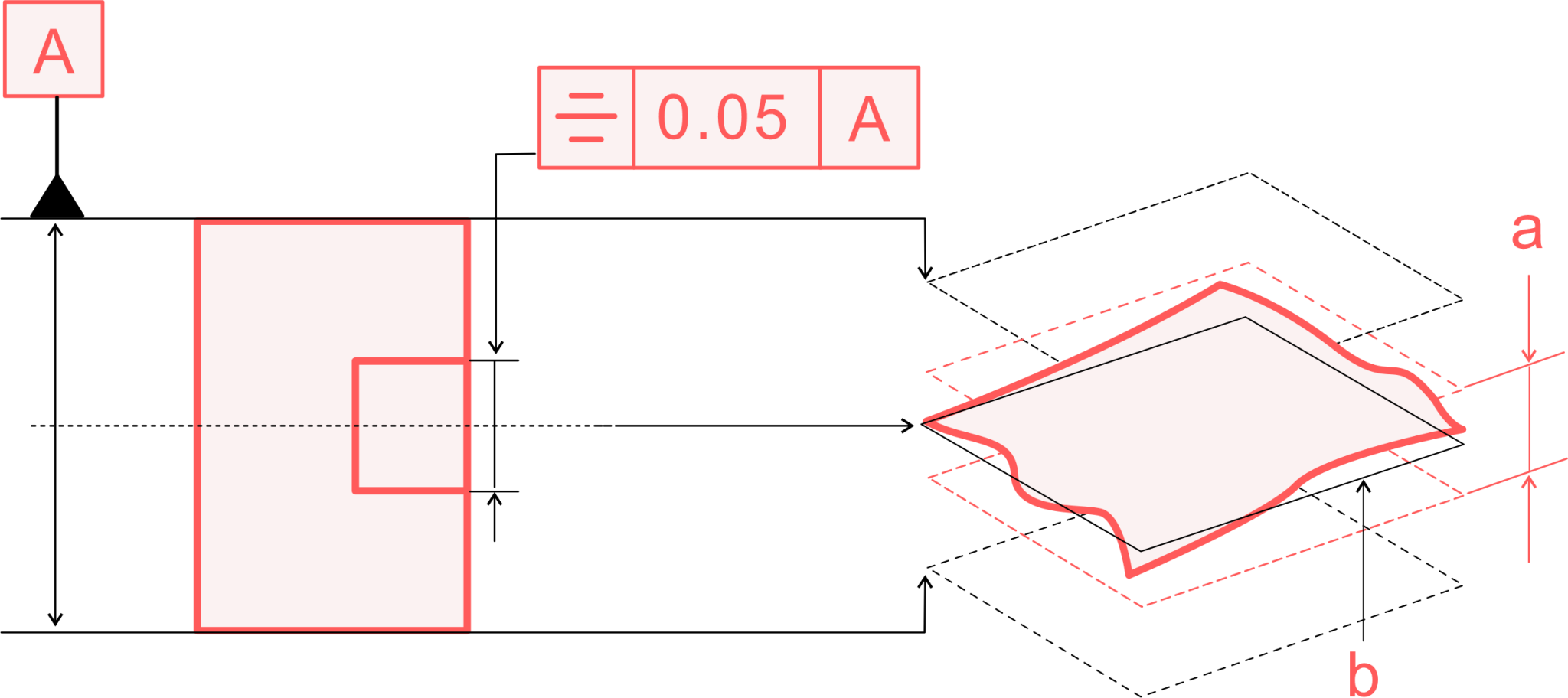
 GD&T Symmetry is a 3D geometric tolerance that makes sure the median points of a feature are perfectly centred around a datum centre plane or datum axis. This symmetry control is used on slots, grooves, and parallel surfaces that must stay balanced and properly located.
Symmetry is a derived feature. We do not measure the feature surfaces directly. Instead, we find the midpoint between two corresponding points on opposite surfaces. The symmetry tolerance says all of these median points must fall within a narrow zone centred on the datum.
This is different from a simple dimensional check. A dimension tells you the size of a slot. The symmetry callout tells you where the centre of that slot must be relative to the datum reference frame.
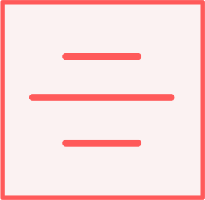 The GD&T Symmetry symbol looks like three short, equal-length horizontal lines stacked on top of each other. You won't see it by itself. It always appears inside a feature control frame (FCF) on the engineering drawing.
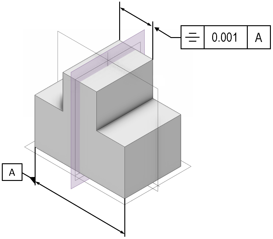
The FCF is a rectangle divided into three compartments. The first contains the Symmetry symbol. The second contains the symmetry tolerance value (for example, 0.03 mm), which defines the total width of the tolerance zone. The third is the datum reference letter (for example, A), which tells you which datum plane the feature must be centred about.
The symmetry callout is always applied RFS (Regardless of Feature Size). This means the symmetry tolerance applies at whatever actual size the feature is produced. There are no bonus tolerances, and material condition modifiers like MMC or LMC cannot be used with this symmetry control.
What Is GD&T Symmetry?
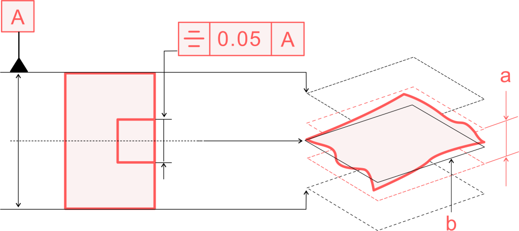
GD&T Symmetry is a 3D geometric tolerance that makes sure the median points of a feature are perfectly centred around a datum centre plane or datum axis. This symmetry control is used on slots, grooves, and parallel surfaces that must stay balanced and properly located.
Symmetry is a derived feature. We do not measure the feature surfaces directly. Instead, we find the midpoint between two corresponding points on opposite surfaces. The symmetry tolerance says all of these median points must fall within a narrow zone centred on the datum.
This is different from a simple dimensional check. A dimension tells you the size of a slot. The symmetry callout tells you where the centre of that slot must be relative to the datum reference frame.
Symmetry Symbol
The GD&T Symmetry symbol looks like three short, equal-length horizontal lines stacked on top of each other. You won't see it by itself. It always appears inside a feature control frame (FCF) on the engineering drawing.
The FCF is a rectangle divided into three compartments. The first contains the Symmetry symbol. The second contains the symmetry tolerance value (for example, 0.03 mm), which defines the total width of the tolerance zone. The third is the datum reference letter (for example, A), which tells you which datum plane the feature must be centred about.
The symmetry callout is always applied RFS (Regardless of Feature Size). This means the symmetry tolerance applies at whatever actual size the feature is produced. There are no bonus tolerances, and material condition modifiers like MMC or LMC cannot be used with this symmetry control.
Symmetry Tolerance Zone
The area where all the median points must fall is called the symmetry tolerance zone. It consists of two parallel planes equally spaced on either side of the datum centre plane. These virtual tolerance zone planes define the boundary for every median point on the controlled feature. If the feature control frame specifies a symmetry tolerance of 0.03 mm, each plane sits 0.015 mm from the datum center plane. The total zone width is 0.03 mm, perfectly centred on the datum plane. The tolerance value is always the total width. A callout of 0.03 mm means 0.015 mm on each side, not 0.03 mm on each side. The center plane shown on the drawing is the theoretical center plane of the datum. The tolerance zone is built symmetrically around it. All of the median points must fall within this tolerance zone to pass inspection. If any median point moves outside of these two parallel planes, the part does not meet the symmetry requirement.Symmetry Tolerance Example
Consider a steel shaft with a 40 mm outer diameter and a keyway slot (10 mm wide, 4 mm deep) that must mate with a drive key. The symmetry requirement specifies centring on the shaft's vertical centre plane (Datum A) to within 0.05 mm. The feature control frame reads: Symmetry | 0.05 | A. The symmetry tolerance zone consists of two parallel planes spaced 0.025 mm on each side of Datum A's centre plane, for a total zone width of 0.05 mm. During CMM inspection, the derived median points from opposite walls of the keyway must all fall within this zone. Each measurement point is compared against the theoretical center datum. If the keyway drifts to one side, the drive key binds against one wall and concentrates stress there, increasing fatigue cracking risk. A symmetrical keyway distributes torque evenly across both walls. That is why the symmetry tolerance is specified here rather than a simple dimensional check.How to Measure Symmetry
Symmetry is one of the hardest GD&T callouts to verify because we are measuring derived median points, not actual surfaces.