Wire EDM: How it Works, Advantages, and Applications
Learn how wire EDM machining works, its key advantages, and where it's used. Discover why wire EDM is ideal for tight tolerances and complex shapes in hard metals.
In precision manufacturing, machining extremely hard materials or ultra-complex geometries often reaches the physical limits of traditional cutting tools. Wire Electrical Discharge Machining (Wire EDM) solves this problem.
It uses thermal energy from controlled electrical sparks instead of physical contact force. The result is micron-level accuracy and smooth surface finishes, regardless of material hardness.
What is Wire EDM?
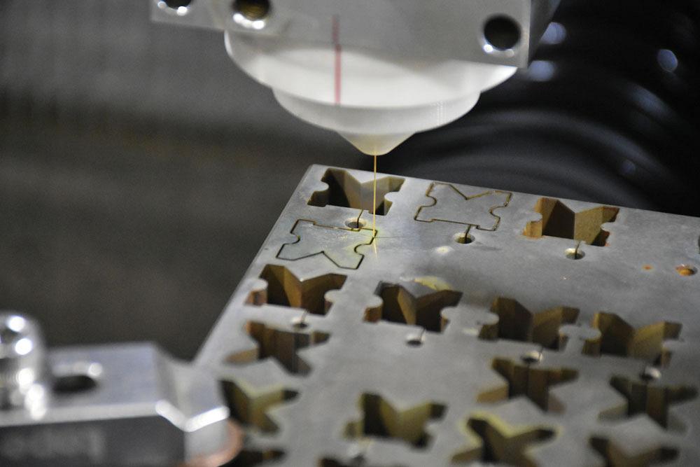
Wire EDMWire EDM (Wire Electrical Discharge Machining), often referred to as wire cutting or wire erosion, is a non-traditional CNC machining process that uses a thin conductive wire (typically brass or coated copper) to cut electrically conductive metals with high precision.
Unlike traditional milling or turning that physically shears away metal shavings, Wire EDM uses high-frequency electro-thermal energy. High-voltage electrical sparks jump between the wire electrode and the conductive workpiece, melting and vaporizing microscopic amounts of metal along a programmed path.
How Does Wire EDM Work?
Wire EDM
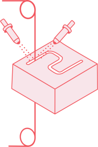
The fundamental principle behind Wire EDM is controlled electrical erosion. The process works in four stages.
#1. Dielectric submersion.
The workpiece is submerged in dielectric fluid (typically deionised water). The fluid acts as an electrical insulator, coolant, and flushing agent. The wire electrode threads through a pre-drilled start hole or begins from the workpiece edge.
#2. Spark generation.
The wire and workpiece connect to a DC power generator. As the wire approaches the workpiece, a tiny spark gap (typically 0.025 mm to 0.05 mm) separates them. When the electric field overcomes the dielectric barrier, a spark jumps across.
#3. Melting and vaporisation.
Tens of thousands of high-frequency sparks fire per second across the gap. Each spark generates localised temperatures of 8,000°C to 12,000°C. This instantaneously melts and vaporises microscopic particles from the workpiece surface. The CNC controller moves the worktable along the X and Y axes to trace the programmed contour.
#4. Flushing and continuous wire feed.
High-pressure dielectric nozzles flush away eroded metallic debris (micro-swarf) to prevent arcing and maintain stable cutting. Fresh wire feeds continuously from a spool, so the cutting electrode never wears down mid-cut.
After the roughing pass, most precision jobs require 2 to 4 additional skim cuts. Each skim cut uses lower power and a smaller offset. This progressively improves dimensional accuracy and surface finish. A well-executed skim cut sequence can achieve tolerances of ±0.002 mm and surface finishes below Ra 0.2 μm.
Wire EDM also supports taper cutting. The upper wire guide shifts independently in the U and V axes, creating an angle between the top and bottom of the cut. Taper angles up to 30° are possible, depending on the machine and workpiece thickness.
Main Components of a Wire EDM Machine
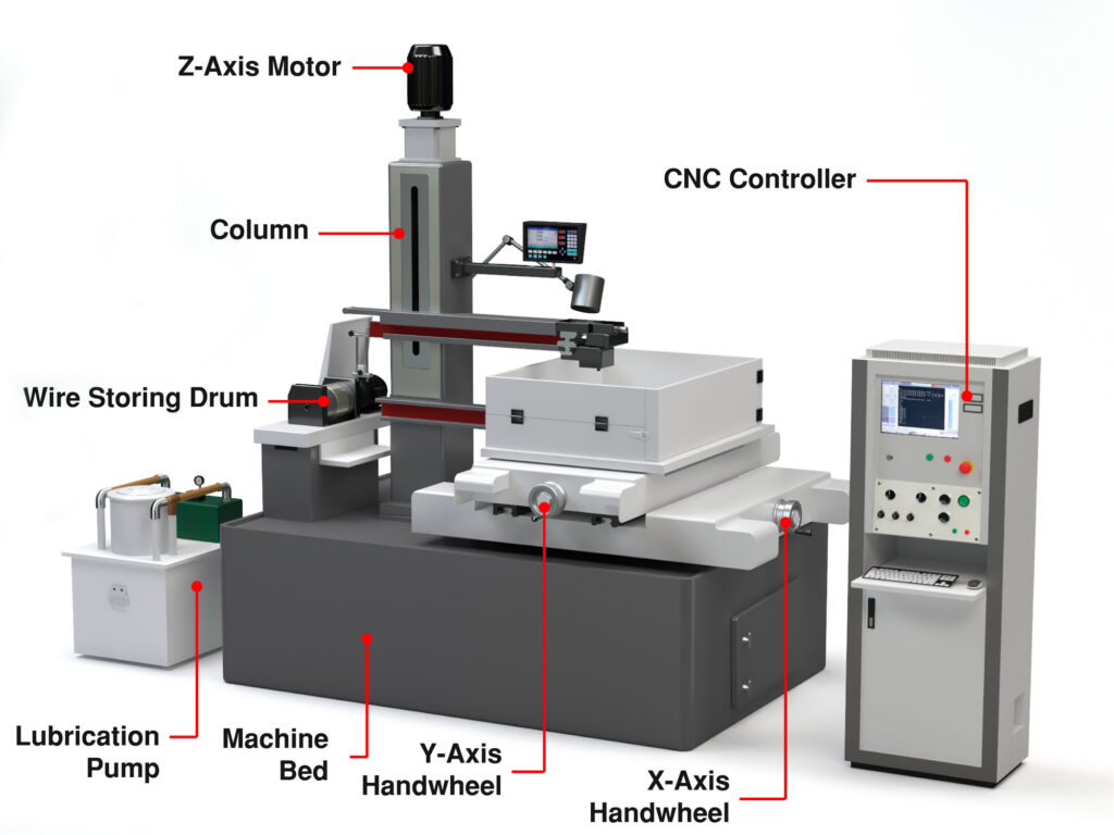
A standard Wire EDM system relies on several integrated subsystems:
Power Supply Generator:Converts AC line power into high-frequency DC electrical pulses. It controls spark energy, frequency, and pulse duration. Higher energy removes material faster but produces a rougher finish.
Wire Electrode:A thin metal wire, commonly brass, zinc-coated brass, or diffusion-annealed copper, with diameters ranging from 0.10 mm to 0.30 mm. Thinner wires allow tighter radii and finer detail. Thicker wires cut faster and resist breakage.
Wire Feed and Tension System:Continuously spools fresh wire through the cutting zone while maintaining precise mechanical tension. Too much tension snaps the wire. Too little causes deflection and reduces accuracy.
Upper and Lower Wire Guides:Precision diamond or sapphire guides positioned above and below the workpiece. They hold the wire to sub-micron accuracy. The upper guide can move independently in the U and V axes to enable taper cuts and 3D contours. Worn guides must be replaced regularly to maintain precision.
Dielectric Fluid System:Circulates and pressurises deionised water to insulate the spark gap, cool the wire, and flush eroded debris. Water resistivity is controlled between 1 and 20 MΩ·cm via a deioniser unit.
Filtration System:Removes metallic micro-particles from the dielectric fluid using paper or cartridge filters. Some machines also use resin beds to maintain water purity. Contaminated fluid causes unstable sparking and poor surface finish.
CNC Controller:Executes G-code, manages multi-axis movement (X, Y, Z, U, V), and adjusts spark parameters dynamically. Modern controllers include automatic wire threading (AWT) and adaptive power control.
Working Table:A rigid worktable mounted inside the dielectric tank. It moves in X and Y on precision linear guides. The workpiece is clamped, fixtured, or magnetically held to the table surface.
Which Materials Can Be Processed with Wire EDM?
Wire EDM can cut any electrically conductive material, regardless of its physical hardness, heat treatment state, or toughness.
Exotic Alloys:Titanium, Inconel, Monel, Hastelloy, and Waspaloy.
Refractory Metals:Tungsten, molybdenum, and tantalum.
Carbides and Superhard Materials:Tungsten carbide, sintered carbide components, and polycrystalline diamond (PCD).
Standard Conductive Metals:Aluminium, copper, brass, and bronze.
Material hardness does not affect cutting speed. A piece of hardened D2 at 62 HRC cuts at roughly the same rate as mild steel of the same thickness. This makes Wire EDM ideal for machining pre-hardened tooling components without additional heat treatment steps.
Non-conductive materials such as thermoplastics, glass, ceramics, and composites cannot be machined using Wire EDM.
Key Advantages and Limitations
Advantages
No direct cutting force.The wire never touches the material. Zero mechanical stress or tool pressure. This allows ultra-thin walls, delicate webs, and fragile geometries without distortion.
Extreme precision.Achieves tolerances down to ±0.002 mm with surface finishes below Ra 0.2 μm. Multiple skim cuts progressively refine both accuracy and finish quality.
Hardness immunity.Easily cuts through fully hardened steel (60+ HRC) and tungsten carbide without tool wear or the need for annealing.
Tight internal corners.Can machine internal radii down to 0.05 mm. Standard rotary milling cutters cannot achieve this.
Minimal heat-affected zone.The dielectric fluid cools the cut zone effectively. The HAZ is typically under 0.01 mm, far thinner than laser cutting or conventional machining. This preserves the metallurgical properties of the base material near the cut edge.
Burr-free results.Leaves clean edges with no burrs, flash, or chatter marks. Manual deburring is eliminated in most cases.
Limitations
Conductive materials only.Non-conductive materials such as plastics, glass, and most ceramics cannot be processed.
Through-cuts only.Wire EDM cuts through the full thickness of the workpiece. It cannot machine pockets, cavities, or blind features. Those require sinker EDM or CNC milling.
Slower material removal rate.Compared to high-speed CNC milling, volumetric stock removal is slower. Wire EDM is less suitable for heavy roughing of large blocks.
Requires starter holes.Internal cutouts require pre-drilled entry holes (typically via EDM hole drilling) to thread the wire through before cutting.
Recast layer.High spark temperatures create a microscopic hardened recast layer (0.001 to 0.005 mm). For critical aerospace or medical fatigue applications, light polishing or secondary finishing may be needed to remove it.
Applications of Wire EDM
Wire EDM is widely used across industries that demand precision, tight tolerances, and complex shapes in hard materials.
Tool and die making.Blanking dies, progressive stamping dies, extrusion dies, and mould inserts. Wire EDM cuts pre-hardened tool steel directly, eliminating the need for post-machining heat treatment and secondary finishing.
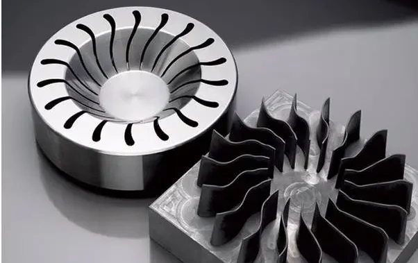
Turbine blades, fir-tree slots, fuel nozzle components, and high-temperature alloy structural brackets. Wire EDM handles Inconel, titanium, and other superalloys that resist conventional cutting tools.
Medical devices.Surgical instruments, orthopaedic implants, biopsy forceps, and custom titanium components. The burr-free edges and fine surface finish reduce post-processing for medical-grade parts.
Transmission components, fuel injector nozzles, and gear profiles. Wire EDM produces high-precision features in hardened automotive steels where CNC milling would require special tooling.
Gear and spline manufacturing.Internal and external gear profiles, splines, and keyways. Wire EDM cuts precise tooth forms and tight internal radii that hobbing or shaping cannot achieve.
Micro-fixtures, lead frames, and high-precision contacts. Fine wire (0.05 to 0.10 mm) enables micro-EDM work for miniature components.
Prototyping and low-volume production.Complex 2D profiles and gears without expensive custom tooling. Wire EDM needs only a CNC program and a start hole, making it cost-effective for short runs and design validation.
Wire EDM vs Sinker EDM
Both processes use electrical discharge erosion, but their electrode style and applications differ significantly.
Feature
Wire EDM
Sinker EDM (Ram/Die-Sinking)
Electrode Type
Continuous spool of thin wire
Custom-machined 3D electrode (copper/graphite)
Cutting Action
2D/taper through-cutting (like a band saw)
3D cavity sinking (plunges down into workpiece)
Blind Cavities
No (requires a through-hole or edge start)
Yes (ideal for blind keyways and mould cavities)
Tooling Cost
Very low (standard wire spools)
Higher (requires machining custom electrodes)
Accuracy
±0.002 to ±0.005 mm
±0.005 to ±0.015 mm
Surface Finish
Ra 0.1 to 0.4 μm
Ra 0.4 to 1.6 μm
Setup Time
Fast (CNC program + start hole)
Slow (electrode must be designed and machined first)
When to choose Wire EDM: You need a through-cut profile with tight tolerances and fine surface finish. Die openings, punch profiles, and precision contours are ideal.
When to choose Sinker EDM: You need a cavity, pocket, or 3D shape that does not go through the full thickness. Injection mould cavities, rib details, and textured surfaces are typical sinker EDM work.
Wire EDM vs Laser Cutting
Both Wire EDM and laser cutting produce precise profiles from sheet and plate materials, but they use very different energy sources and suit different applications.
Feature
Wire EDM
Industrial Fibre Laser Cutting
Mechanism
Electrical spark erosion
Thermal fibre laser beam
Material Requirement
Must be electrically conductive
Metals, plastics, wood, composites
Cutting Speed
Slow (100 to 300 mm²/min)
Very fast (several metres per minute on thin sheet)
Max Thickness
Up to 300 to 500 mm
Typically under 25 mm for precision cuts
Accuracy
±0.002 to ±0.005 mm
±0.05 to ±0.1 mm
Heat-Affected Zone
Minimal (under 0.01 mm)
Noticeable (0.1 to 0.5 mm)
Edge Quality
Perpendicular edges, mirror-level finish
Slight taper, potential slag on bottom edge
Best Used For
Thick, high-precision dies and tooling
Sheet metal fabrication and high-volume blanks
When to choose Wire EDM: You need extreme precision, fine surface finish, or you are cutting thick conductive material. Parts with tolerances under ±0.01 mm or surface finish requirements below Ra 1.0 μm are suited for Wire EDM.
When to choose laser cutting: You need speed, high volume, or you are cutting thin sheet metal and non-metallic materials. Laser cutting is far more productive for parts where tolerances of ±0.1 mm are acceptable.
Wire EDM vs CNC Milling
CNC milling is the most common subtractive manufacturing process. Wire EDM is a specialist process. They overlap in some applications but serve different roles.
Feature
Wire EDM
CNC Milling
Tool Type
Charged wire electrode (non-contact)
Rotating fluted cutters (physical contact)
Tool Wear
Wire is constantly refreshed from spool
Cutting tools wear out and break
Material Hardness Impact
Hardness does not affect cutting speed
Harder metals wear tools rapidly and slow feed rates
Feature Types
Through-cuts only
Pockets, slots, holes, 3D surfaces, and through-cuts
Geometry Strengths
Sharp internal corners, tall thin walls
Complex 3D sculpted surfaces and pockets
Setup and Forces
Zero cutting forces, simple clamping
High cutting forces, rigid workholding required
Accuracy
±0.002 to ±0.005 mm
±0.01 to ±0.025 mm (standard); ±0.005 mm (high-precision)
Material Removal Rate
Low (100 to 300 mm²/min)
High (orders of magnitude faster)
When to choose Wire EDM: The material is too hard for milling. The tolerances are tighter than CNC milling can achieve. The geometry has sharp internal corners or thin walls that cutting forces would damage.
When to choose CNC milling: You need 3D features like pockets and contours. The production volume is high. The material is soft enough for conventional cutting tools. Speed and cost efficiency matter more than extreme precision.

 Wire EDM
 Wire EDM
 A standard Wire EDM system relies on several integrated subsystems: